Power Monitor
...Back to Projects:
The Power Monitor Board
Introduction
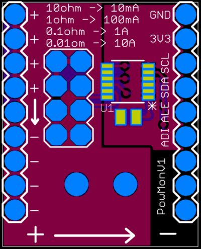
Based on the LTC2945, this board can measure Voltage, Current, and Power. Communication to the board to read out the values (among many other parameters) is done over a simple I2C interface. It uses a sense resistor to measure the current with varying degrees of resolution based on the value. The board has been designed to allow changeable sense resistors:
- 10 ohm = 10mA Max Current with 2.5uA Resolution
- 1ohm = 100mA Max Current with 25uA Resolution
- 0.1 ohm = 1A Max Current with 250uA Resolution
- 0.01 ohm = 10A Max Current with 2.5mA Resolution
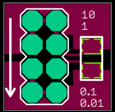
Each of these resistors can be soldered onto a mini Current Sense Board, then based on the expected max current of the project, the appropriate Current Sense Board can be plugged into the Power Monitor Board.
Other features include min/max logging of the values, programmable alarm thresholds with dedicated alarm output(ALE), and an auxiliary 2.048V Analog Input (AIN).
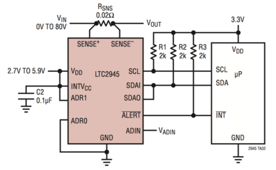
Though, the board shows 3V3, the board is also compatible with 5V systems. This configuration from the datasheet was implemented:

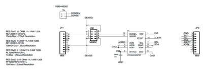
Schematic
Purchase
Coming soon - given to Patrons ...


