Difference between revisions of "CameraBoard"
From Kevin Darrah Wiki
(Created page with "...Back to Projects: 600px The Weather Board is a breakout for the [https://www.bosch-sensortec.com/bst/products/all_products/bme280 BME280] (Tem...") |
|||
| (6 intermediate revisions by the same user not shown) | |||
| Line 1: | Line 1: | ||
...Back to [[Projects:]] | ...Back to [[Projects:]] | ||
| − | [[File: | + | [[File:trigCam.png|400px]] |
| − | The | + | The Camera Board is an adapter to allow the [https://www.amazon.com/gp/product/B012UXNDOY/ref=oh_aui_detailpage_o02_s00?ie=UTF8&psc=1 ArduCam] to pair up with the [[trigBoard]]. But really this project can be applied to any ESP8266 breakout, just as long as the connections match up. |
| − | [[File: | + | [[File:camBoardGerb.png|200px]] |
| − | + | == Schematic == | |
| − | + | [[File:Screen Shot 2018-03-03 at 3.14.06 PM.png|800px]] | |
| − | + | ||
| − | + | == Assembly == | |
| − | | | + | |
| − | + | The camera board installs in the same way the [[WeatherBoard]] did - just lay small pieces of wire or leads to connect the pads. Just keep in mind that you'll have to tie into pin 4 of the ESP-12 module. See the back side of the board below: | |
| + | |||
| + | [[File:cameraFront.png|400px]] | ||
| − | + | [[File:cameraBack.png|400px]] | |
| − | + | == CODE == | |
| − | + | Built off the base code, this adds support for the Arducam: | |
| + | [http://www.kevindarrah.com/wp-content/uploads/2018/03/trigBoard_ArduCam_RELEASED_3_29_18.zip trigBoard_ArduCam_RELEASED_3_29_18] | ||
| − | + | and the PHP code you upload to the server you want to store the images: | |
| + | [http://www.kevindarrah.com/wp-content/uploads/2018/03/frommicro.php_.zip frommicro.php] | ||
| + | This will go into the folder where you want the images to be stored, just remember to add an images folder and an index.html file. It should look like this: | ||
| + | [[File:cameraFolder.png|800px]] | ||
| − | + | == Tutorial == | |
{{#evt: | {{#evt: | ||
service=youtube | service=youtube | ||
| − | |id=https://youtu.be/ | + | |id=https://youtu.be/0VgLEP1ktcg |
|dimensions=560x315 | |dimensions=560x315 | ||
}} | }} | ||
| − | |||
Latest revision as of 16:20, 30 March 2018
...Back to Projects:

The Camera Board is an adapter to allow the ArduCam to pair up with the trigBoard. But really this project can be applied to any ESP8266 breakout, just as long as the connections match up.

Contents
Schematic

Assembly
The camera board installs in the same way the WeatherBoard did - just lay small pieces of wire or leads to connect the pads. Just keep in mind that you'll have to tie into pin 4 of the ESP-12 module. See the back side of the board below:


CODE
Built off the base code, this adds support for the Arducam: trigBoard_ArduCam_RELEASED_3_29_18
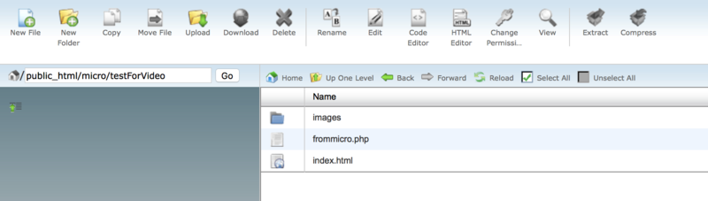
and the PHP code you upload to the server you want to store the images: frommicro.php
This will go into the folder where you want the images to be stored, just remember to add an images folder and an index.html file. It should look like this:
