TrigBoardV7
...Back to Projects:
The trigBoard is an extremely low power platform for the ESP32 WiFi+Bluetooth Module. This board is perfect for battery powered applications, due to it's single digit uA standby current draw ~1.5uA with a 3V battery input. To give an idea as to how low this current draw is, a cheap smoke detector pulls about 7uA. This board was initially designed to be the ideal IoT device - a WiFi connected battery powered monitoring solution for dry contacts (door/window sensors), where a push notification is immediately sent when the contact state has changed. The ultra low standby current does not change regardless if the contact remains in the closed/opened state (this is part of the secret sauce in the trigBoard design). But of course, the trigBoard is a playground of low power features, so it can easily be adapted to a unique monitoring application:
- Many battery options, with input voltage range from 1.8-5V. Great for two AAA batteries or even a rechargeable Lithium cell at 4.2V. Reverse polarity protection built in, so no issues if batteries are plugged in backwards.
- Multiple wake sources all configurable through software (no solder jumpers)
- Dry contact trigger input supporting BOTH contact OPEN and contact CLOSE, but configurable for either or both, so if for example a garage door was monitored, a push notification could go out for when the garage opens AND when the garage closes.
- The board utilizes an actual RTC (Real Time Clock). This is a high quality RTC, so accurate wake times can be configured. The timer wakes the board up at the configured time - for example once and hour, then checks the battery voltage and if low, will send out a push notification. The timer can also be used to check the current status of the contact and send out a notification, so in the garage door example, the board can be configured to not only send out notifications when the door opens/closes, but also when the garage is left open for some period of time after the door was opened.
- Wake button on board can also be used to send out a push notification.
- Unused pins from ESP32 broken out for future expansion and in-line to fit breadboards - developer friendly.
- Base Firmware supports many Push Notification service options like Pushsafer, Pushover, and IFTTT. And even develop a custom solution with MQTT and UDP messaging. Any of these can be enabled, or even multiple. For example, the notifications can go out through Pushover, then a secondary backup notification can go through MQTT. Or even a notification though Pushsafer, then turn the lights on in the house with IFTTT. The possibilities are endless with this.
- Configuration software gives full control over the board parameters and settings - in a nice clean easy to use GUI through Google Chrome and a Bluetooth connection to the ESP32.
Latest Release Version 8
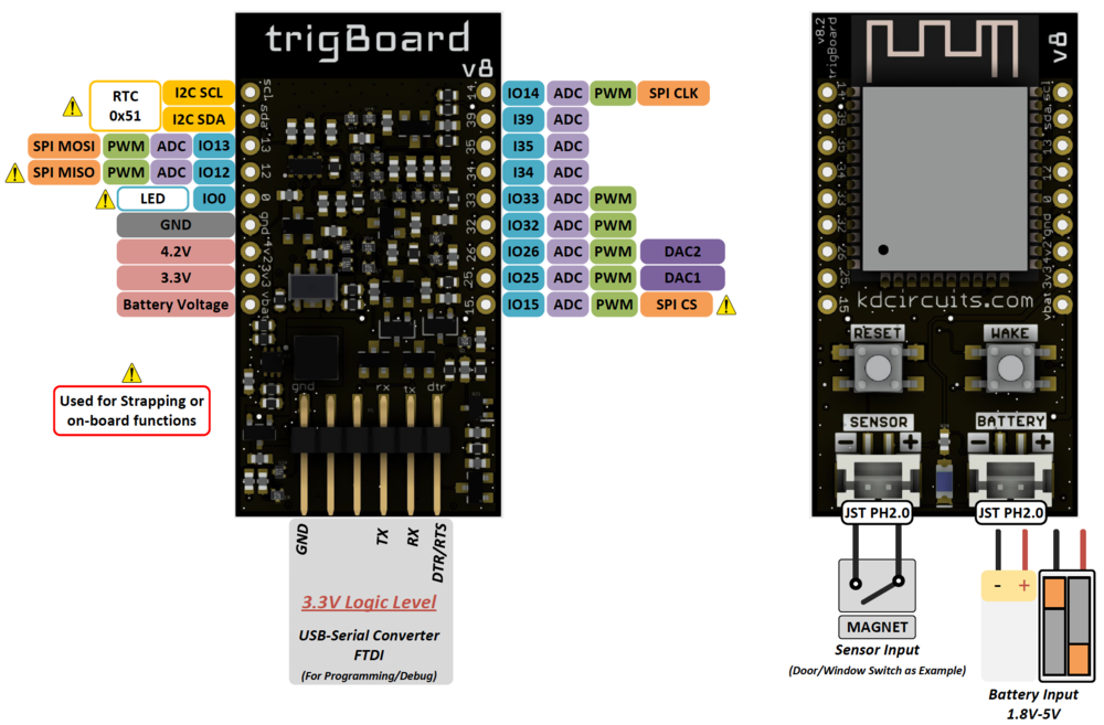
For expansion - randomnerdtutorials.com has a great guide on what pins do what. Just be careful with the pins marked above with the hazard symbol. These pins can be used, but just make sure that the mode they're configured for does not interfere with the normal operation of the board. For example, the GPIO12 cannot be held high during boot up, or the ESP32 will never fully boot up and execute the code. Also, on board is an RTC using the I2C port, so that same port can be used for other I2C devices, just as long as there's no address conflict.
trigBoard Pin Usage At the core of the trigBoard, it's just a tricked out ESP32 development board with some incredible low power capability. Power is actually removed from the ESP32 in order to accomplish the single digit uA standby current. This is important to note since the 3.3V rail is controlled by the wake circuitry. If needed, the base firmware can be completely overwritten by whatever custom application that fits the needs of the user. These are the pins used by the wake circuitry on the trigBoard, which can be used by the user for the custom application:
IO36 AINPUT Battery Pin for analog measurements of the battery voltage
IO0 OUTPUT LED pin - drive low to turn LED ON, but be careful with this pin, since also used by the auto reset circuitry.
IO16 OUTPUT Power Latch Pin - this pin can be driven high to keep power latched to the ESP32. When the board wakes up, this pin is driven HIGH immediately to keep power applied while the wake source is determined and unlatched. When the board is ready to go back to sleep, this pin can be written LOW.
IO17 OUTPUT Kill Power Pin or UnLatch Pin - The sensor input utilizes two latches for the normally open/closed inputs. When the board wakes, these latch inputs can be read in, then unlatched with this pin by writing it HIGH.
IO18 INPUT Contact Opened Latch Pin - If low, the sensor input has got from closed to open.
IO19 INPUT Contact Closed Latch Pin - If low, the sensor input has got from open to closed.
IO23 INPUT Contact Status Pin - real time status of the contact - HIGH = Contact is OPEN, LOW = Contact is CLOSED
IO27 INPUT Wake Button Pin - LOW = Button was pressed
IO21 & IO22 Used by the RTC at address 0x51
Purchase trigBoard
v8 to be ready soon...
Out of the Box Setup
The trigBoard v8 ships preloaded with base firmware, so it's very easy to get up and running.
- Hardware Setup All that's needed here is a battery and a dry contact used for triggering. Both connectors on the board are standard JST PH 2.0mm
- Battery Selection A good capacity for the trigBoard is 500-1000mAh, but this depends on how often the board will be triggered. Any of these Lithium batteries would work from Adafruit. Or two AA or AAA batteries would work, with a holder like this
- Sensor These door sensors from Amazon work really nice, especially since they can be wired to directly. This allows for any wire length that is needed. The PH2.0 cable can also be found on Amazon like these if it has to be a little longer. Note that the polarity of the sensor input does not matter.
- Push Notification Service The trigBoard's base firmware supports various services, including Pushsafer, Pushover, IFTTT, and can even send messages over MQTT and UDP. Before doing anything with the TrigBoard, the service must be chosen and ready to go. Here's what's needed for each of them:


