Difference between revisions of "328Board"
| (20 intermediate revisions by the same user not shown) | |||
| Line 1: | Line 1: | ||
...Back to [[Projects:]] | ...Back to [[Projects:]] | ||
| − | [[File:328gerber.png|300px]] | + | |
| + | <!--[[File:328inhand.png|300px]]--> | ||
| + | [[File:328wquarter.png|300px]] | ||
| + | <!--[[File:328gerber.png|300px]]--> | ||
= The 328 Board = | = The 328 Board = | ||
== Introduction == | == Introduction == | ||
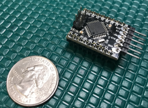
| − | The 328 board is a bare bones breakout board for the ATMEGA328P. Nearly all of the IO has been broken out to standard 0.1" spaced through holes, which also fits nicely into one of the slots of the [[PlatformBoard | Platform Board]] | + | The 328 board is a bare bones breakout board for the ATMEGA328P. Nearly all of the IO has been broken out to standard 0.1" spaced through holes, which also fits nicely into one of the slots of the [[PlatformBoard | Platform Board]] or right into your breadboard. It's also small enough to embed into your final project. |
| + | * Uses the very popular [http://www.atmel.com/images/Atmel-8271-8-bit-AVR-Microcontroller-ATmega48A-48PA-88A-88PA-168A-168PA-328-328P_datasheet_Complete.pdf ATMEGA328P] Microcontroller with 32k of Flash Memory, 2k of RAM, and 1k of Non-Volitale Memory (EEPROM) | ||
| + | * Very Small Form Factor 0.8x1.0" or 20.32x25.4mm | ||
| + | * Compatible with the Arduino IDE and comes pre-programmed with the Arduino Mini (ATMEGA328) boot loader. | ||
| + | * Native x6 pin AVR header (ICSP) and x6 pin FTDI header both populated for a very flexible programming experience. | ||
| + | * Clocked at 16MHz with an external crystal | ||
== Pinout == | == Pinout == | ||
| − | [[File:328diagram.png| | + | [[File:328diagram.png|900px]] |
== Schematic == | == Schematic == | ||
| − | |||
[[File:328sch.png|500px]] | [[File:328sch.png|500px]] | ||
== Purchase == | == Purchase == | ||
| − | + | ||
| + | [[File:tindie-larges.png|link=https://www.tindie.com/stores/kdcircuits]] | ||
== Parts == | == Parts == | ||
| − | + | The parts list can be downloaded [http://www.kevindarrah.com/wp-content/uploads/2016/10/328-board-v1_BOM.xlsx **HERE**]. This can be directly uploaded into [https://www.digikey.com Digikey] if you'd like. | |
== Assembly == | == Assembly == | ||
| − | |||
Here is what the board looks like when assembled - the only missing components here are the 9 pin headers and the x6 pin AVR programming header | Here is what the board looks like when assembled - the only missing components here are the 9 pin headers and the x6 pin AVR programming header | ||
| Line 59: | Line 66: | ||
[[File:328usbserial.png|500px]] | [[File:328usbserial.png|500px]] | ||
| + | |||
| + | [[File:328programmed.png|400px]] | ||
== Tutorials == | == Tutorials == | ||
| − | + | ||
| + | Getting Started with the 328 Board | ||
| + | |||
| + | {{#evt: | ||
| + | service=youtube | ||
| + | |id=https://youtu.be/agjYkpx41cQ | ||
| + | |dimensions=560x315 | ||
| + | }} | ||
| + | |||
| + | Most computers either come with the FTDI drivers or will automatically go out and install them, but just in case, here they are http://www.ftdichip.com/Drivers/VCP.htm | ||
| + | and of course, check out the wiki for the USB to Serial Converter Board: [[The_USB_to_Serial_Converter:|HERE]] | ||
Latest revision as of 09:14, 25 September 2018
...Back to Projects:
Contents
The 328 Board
Introduction
The 328 board is a bare bones breakout board for the ATMEGA328P. Nearly all of the IO has been broken out to standard 0.1" spaced through holes, which also fits nicely into one of the slots of the Platform Board or right into your breadboard. It's also small enough to embed into your final project.
- Uses the very popular ATMEGA328P Microcontroller with 32k of Flash Memory, 2k of RAM, and 1k of Non-Volitale Memory (EEPROM)
- Very Small Form Factor 0.8x1.0" or 20.32x25.4mm
- Compatible with the Arduino IDE and comes pre-programmed with the Arduino Mini (ATMEGA328) boot loader.
- Native x6 pin AVR header (ICSP) and x6 pin FTDI header both populated for a very flexible programming experience.
- Clocked at 16MHz with an external crystal
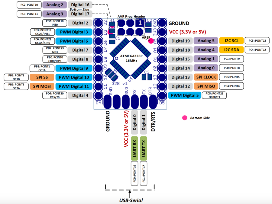
Pinout
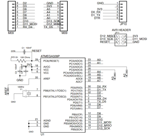
Schematic
Purchase
Parts
The parts list can be downloaded **HERE**. This can be directly uploaded into Digikey if you'd like.
Assembly
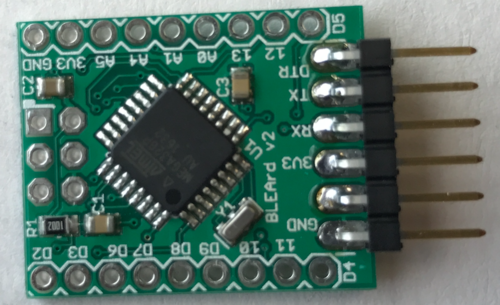
Here is what the board looks like when assembled - the only missing components here are the 9 pin headers and the x6 pin AVR programming header
And here's a video showing how I actually hand assembled this board:
I buy the stainless stencils here: http://www.electrodragon.com/product-category/new-products/pcb-service-new-products/
Plastic Stencils here: https://www.pololu.com/product/446
Hot Air Station here: https://www.amazon.com/gp/product/B00ITMPQS2/ref=oh_aui_detailpage_o04_s00?ie=UTF8&psc=1
Solder Paste: SMD291SNL10 (I keep mine refrigerated when not in use, then sit out for an hour or so before I need it)
https://www.digikey.com/product-detail/en/chip-quik-inc/SMD291SNL10/SMD291SNL10-ND/2057272
Programming
If you want to be able to program the ATMEGA 328 from the Arduino IDE, then you'll need to first load the boot loader. My preferred method is to use Nick Gammon's sketch running on another Arduino:
 A big thanks to Nick Gammon for putting this together:  http://www.gammon.com.au/bootloader
 The git hub link is here:
 https://github.com/nickgammon/arduino_sketches
 Click the Download Zip button, then pull out the Atmega Programmer folder and drop that right into your Sketches folder"
 Another way to do it:
 https://github.com/bkibby/OptiLoader
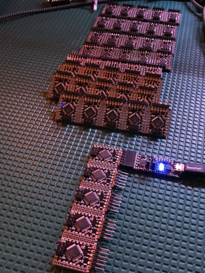
Note - from the board selection, if you're running at 16MHz, then select Arduino Mini, 328 processor. Then you're all set to use the USB-Serial Converter with the 328 board:
Tutorials
Getting Started with the 328 Board
Most computers either come with the FTDI drivers or will automatically go out and install them, but just in case, here they are http://www.ftdichip.com/Drivers/VCP.htm
and of course, check out the wiki for the USB to Serial Converter Board:  HERE
