Difference between revisions of "Stepper Board"
From Kevin Darrah Wiki
| Line 15: | Line 15: | ||
== Schematic == | == Schematic == | ||
| − | + | <span style="color:red">red writing</span> | |
[[File:stepperSch.png|800px]] | [[File:stepperSch.png|800px]] | ||
Revision as of 06:47, 31 May 2017
...Back to Projects:
Contents
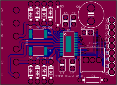
The Stepper Board
Introduction
This board is based on the DRV8825 Stepper Motor Driver. It works with standard x4 wire bipolar stepper motors.
- Motor Voltage Supply from 8.2V to 45V
- Phase Current up to 2.5A, but ~1A is more realistic without a heatsink and fan
- Built in Step Controller, so strap the mode pins for the step mode: Full, Half, and Micro stepping.
- Easy control from a Microcontroller, digital pins to set the direction, enable the part, and step the motor.
- Fault Output Pin broken out and max current setting with a trim pot
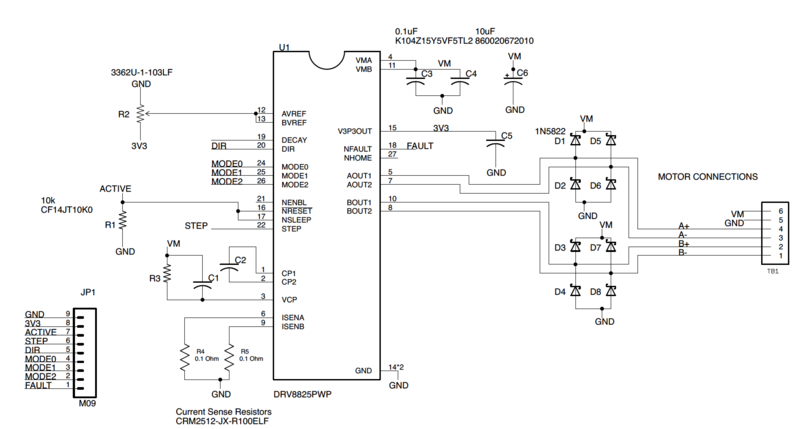
Note that this board breaks out clamping diodes for each of the motor connections - these should not be needed, but I added them in for experimentation purposes.
Schematic
red writing
Purchase
given to Patrons ...
Parts
Parts can be downloaded HERE and uploaded into Digikey
Assembly
Coming Soon...
Tutorials
Little refresher on how stepper motors work:

